GENERAL OVERVIEW
OF ONE ANALYSIS CASE
FOR PRODUCTION
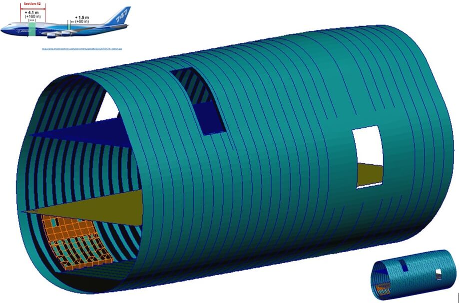
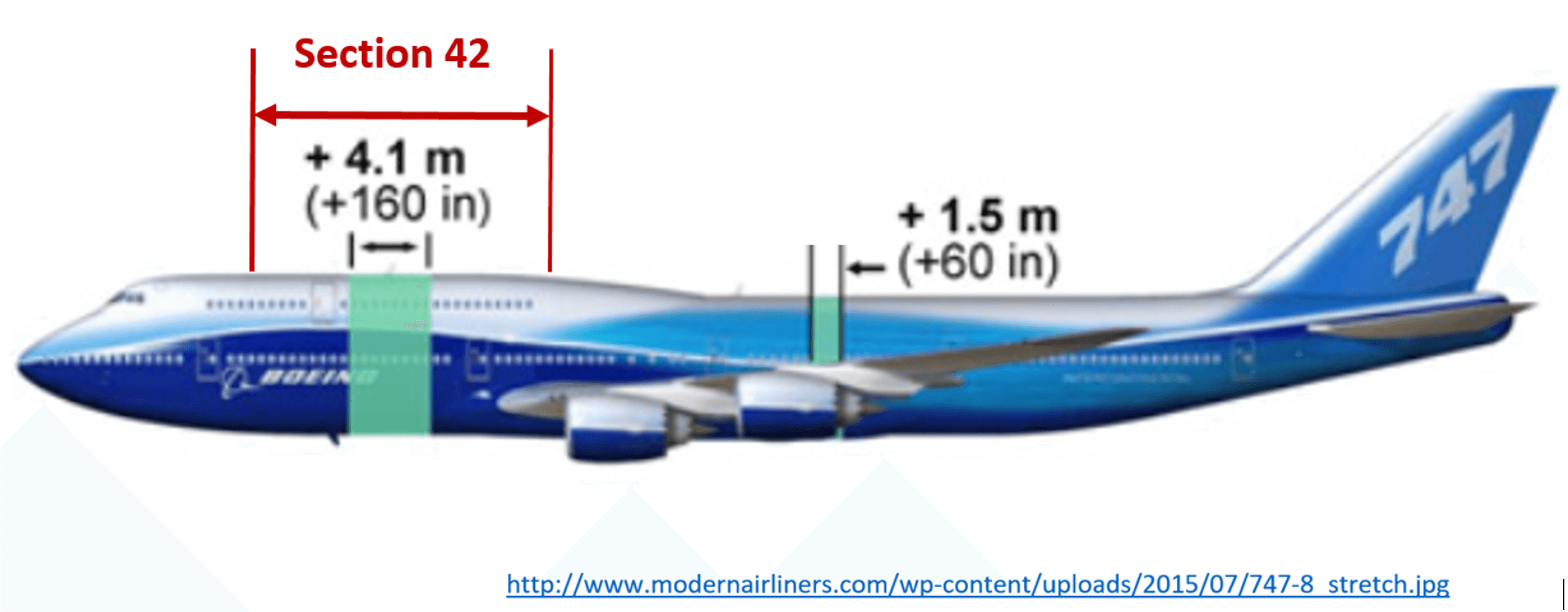
For the last generation of the 747 transport aircraft, the fuselage was increased by 220″(5.6m), with 160″ in Section 42, and 60″ aft of the wing in Section 46. As result of the increased fuselage bending loads, initiation and propagation of fatigue, cracks growing from the corners of the second door needed assessment and preventative measures that accounted for the several missions profiles of this aircraft.
The sizing of the aircraft was based on a “Loads Model” containing the average loads in a bay-by-bay arrangement, with a bay generally being defined as the space between two consecutive frames and two adjacent stringers, or at the middle of the uni-dimensional elements (frame caps and stringers).
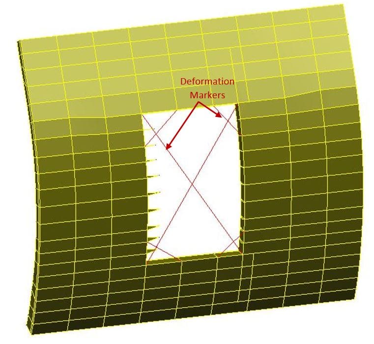
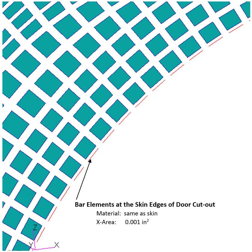
With dimensions of Door 2 being approximately 54″ wide and 82″high, at full-scale, the deformations of the door edges were assessed through thin markers (0.001in2 sections and of small stiffness).
For the fatigue relevant loading situations—defined by over 400 primary external load scenarios, including ground operations, initial and final climbs, gust and manoeuvres, and the descent portions of the flight—localised stresses were required at the corners of the door and at the fastener holes. Fastener loads were also required.
Section 42 Superelemet
(stingers & floor beams not shown)
Top corner: Location of Section 42 and added plugs – click side image to enlarge.
Lower corner: Overview of layout for fuselage reinforcing elements and floor beam arrangement.
FROM GLOBAL LOADS
TO LOCAL STRESSES
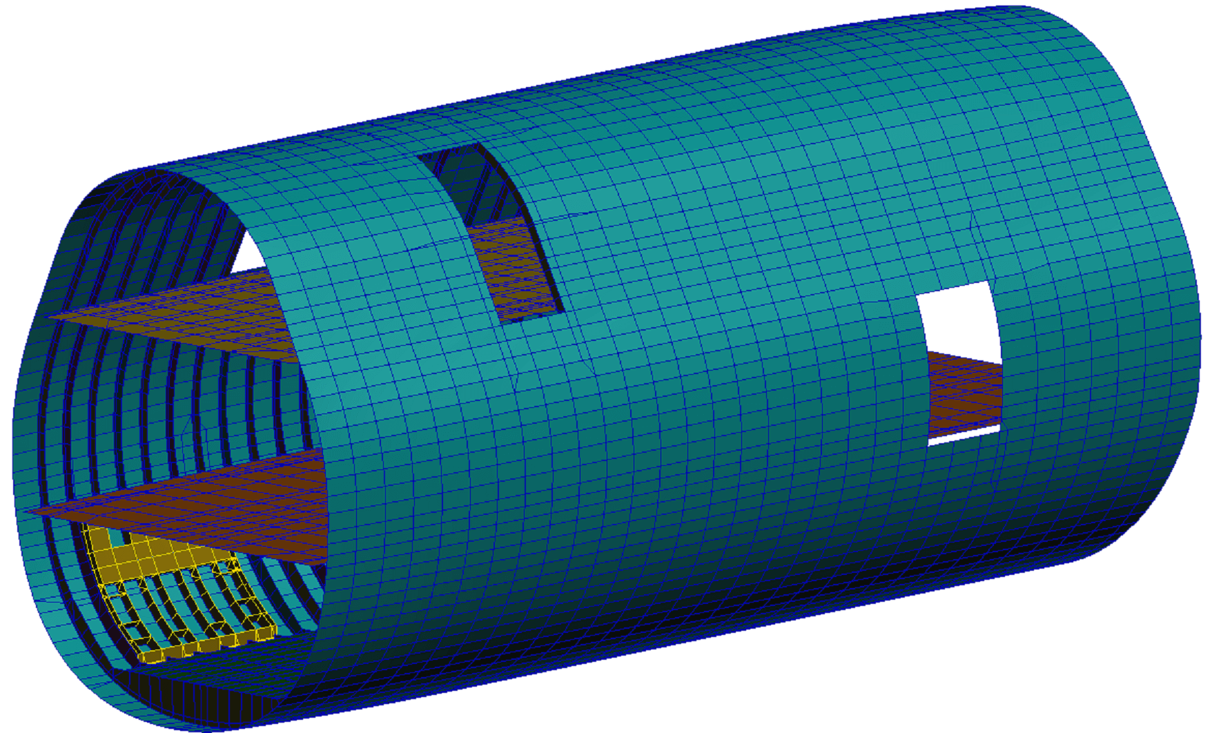
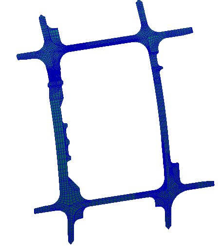
In order to estimate the edge stresses at the corners of aircraft doors, a more detailed model of the door area was generated. Several parts, which were incorporated into the skins or frames in the global model, needed to be represented explicitly—due to some parts being wedged between others—where cracks are difficult to notice during visual or dye-penetrant inspections.
All the newly detailed parts were positioned at the layer of adjacent fuselage skins and the connecting fasteners were modelled with zero-length CBUSH elements.
In order to determine the stresses on the door edges, thin bar elements were added between consecutive nodes along each edge. The material properties of these bars were identical with that of the adjoining skins. Depending on location, the length of these elements varied between 0.05 and 0.2 inch. A similar approach was used for other internal parts ending at, or near to, the edges of the door cut-out.
In this new discretisation, the sub-model was solved using MSC Nastran Solution 101 for all fatigue-relevant load cases, and deformations at the door markers were compared against their values in baseline configuration to ensure that any differences were within acceptable limits. Next, the stress data from the bar elements was processed in order to generate the the fatigue stress spectra for the critical mission profile of different locations, and the fatigue strength at the cut-out was conducted using Boeing’s methods and bespoke software. The specific methodology details used during post-processing are proprietary information of the Boeing Commercial Aircraft company.
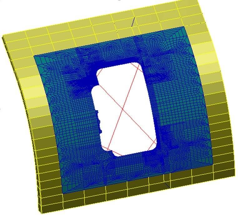
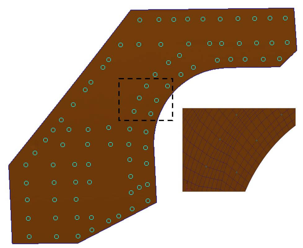
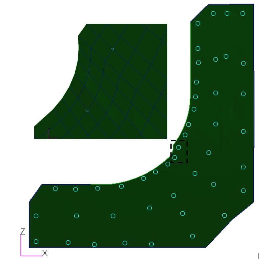
Door 2 area in baseline configuration
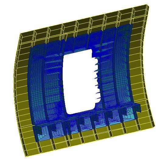
Same area with refined disctretization
TASK RELATED DETAILS FROM
PRODUCTION CONFIGURATION
Currently, two external doublers at top left and lower right corners of Door 2 are being used to reinforce the edges of the fuselage skin. A process, similar to that described above, was used for the analysis of all parts at this location.
Supplementary load transfer values were established at several dozen new fasteners, and these locations were added to the evaluation of fatigue strength. Crack growth analysis was conducted afterwards, using proprietary analysis methods and software.
A. Door 2 analysis area looking from inside
B. Door 2 reinforcing straps (the upper and the lower straps overlap along 30% of their vertical branches)
C. Strain measuring bars along the edges
D. Upper doubler and fasteners
E. Lower doubler and fasteners
FROM OTHER TRANSPORT AND
COMMUTER CATEGORY AIRCRAFT
Sizing of reinforcements for rectangular cut-out in the fuselage of Bombardier G 6000 (in the fuselage crown near the aft pressure bulkhead),
Determination of interface loads at the frames in Section 44 (above the wing) and Section 46 for the installation of Greenpoint Technologies relaxation units in the crown of 747-8,
Verification of the trailing edge panels (composite structure) and the flaps tracks for B 777 F,
Internal structure (spars & ribs) for the wing tip and fences of A 380,
Sizing of reinforcing structure for 14 in circular cutout, located inside the fuselage, aft of main spar (Beach 350)