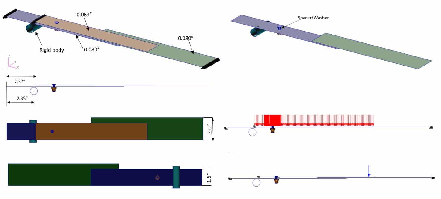
Three aluminium plates, each 10″ long were used to conduct a series of contact analyses in conditions of large deformations and high plastic stresses/strains. The plates arranged as per figure 39, are fixed at the outer ends, with the lower plate resting on a rigid cylinder (R=0.35″) located at approximately a quarter of its total span—initially the plates are just making contact with each other.
Due to the larger width of the middle plate, twisting develops in all parts, causing sideways slipping and non-uniform contact and friction stresses.
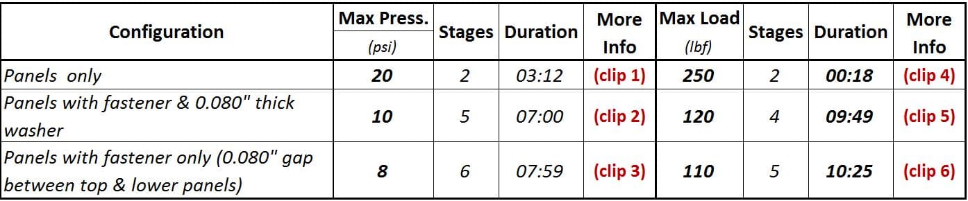
Two types of loading were used: uniform pressure and end loads on the top plate, in three configurations. In the second and third configurations, the top, and the top and lower plates, were joined by one 3/16” Hi-Lok fastener assembly pre-tensioned to 500lbf prior to loading. A 0.080 inch thick washer was included in the second configuration to ensure that the initial contact between the plate was maintained during the fastener installation while, in the third configuration, the washer was removed to allow the external plates to bend freely.
The fastener assembly was included for the purpose of developing a reliable method for fasteners, pre-tensioned or not, that have large positional displacements when connected parts change significantly. Using multi-point constraints (MPC), in explicit form or through the BOLT element, restricts this typeof simulation to assemblies in which the position of the fasteners remain approximately fixed during operation (like the bolts attaching cylinder heads to engine blocks). Videos 1 to 6 show that the approach used enables the fasteners to closely follow a realistic displacement path, maintain pretension and transfer loads without any conflicts with the contact constraints across a large range of deformations.
In the final stage, the load was removed gradually to zero, in order to assess the stress revolutions during this process, and the permanent deformations and residual stresses in the components. Deformations and stress visualisation (von Mises or equivalent non-linear only) for the sliding plates are shown in videos 1 & 4. For configurations with pensioned fasteners, a more detailed review is dedicated to the stress around the mini-plate holes and restraints. Loading and solution parameters, and samples for the iterations histories, are included.