BIOMEDICAL

BRIEF OF SCOPE AND ANALYSIS

A mini-plate for the osteosynthesis of mandibular angle fractures was designed to improve the formation of new bone by reducing—through shape and configuration of holes—the maximum strains that occur in the cortical bone near the first attachment screw, propagating towards the edges of the fracture, through the well-known edge distance effect.


The mini-plate was developed as part of a doctorate program at the Carol Davila University of Medicine and Pharmacy, Bucharest, Romania—with the analyses and FEA simulations preliminary to the development of the new design being done predominantly in Australia. The physical prototypes were CNC machined, tested and inspected afterwards for major mechanical deterioration, or any indications of metal fatigue damage. The new mini-plate has a patent.


For more information on this project, visit ScienceDirect and ResearchGate.

*A. Mandible, mini-plate and screws in finite element discretization
*B. Physical prototype during testing

(wireframe edges removed for clarity)
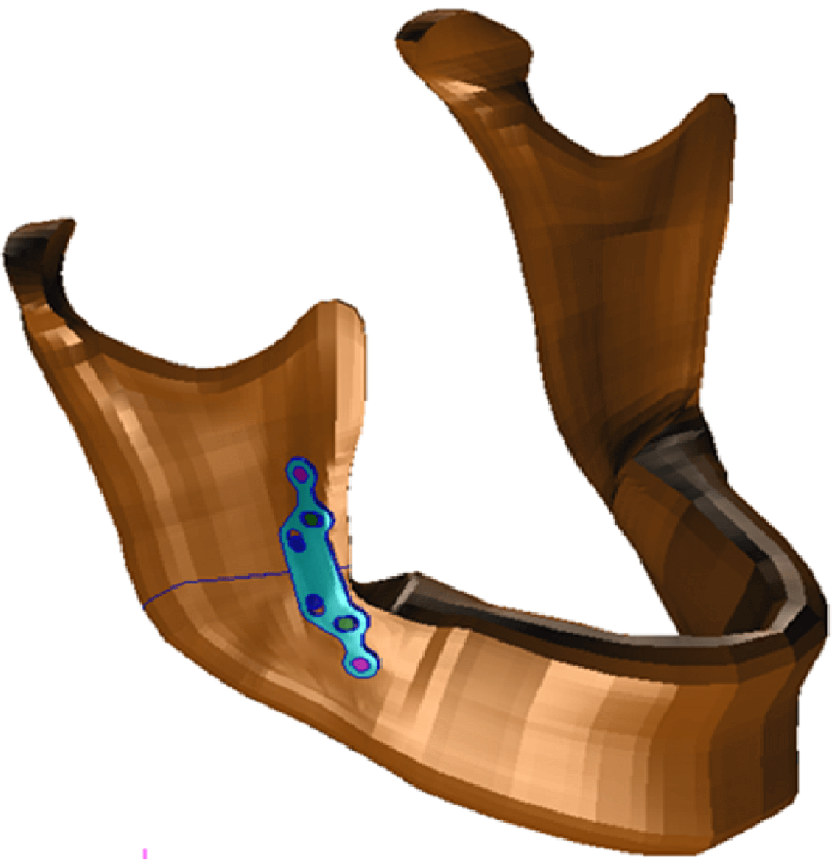
*A. Entire mandible with mini-plate and screws
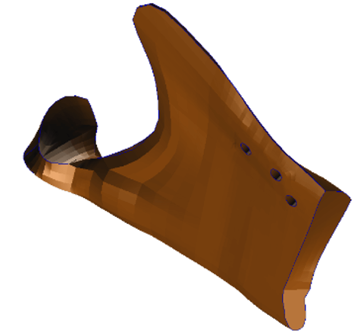
*A. The posterior fragment
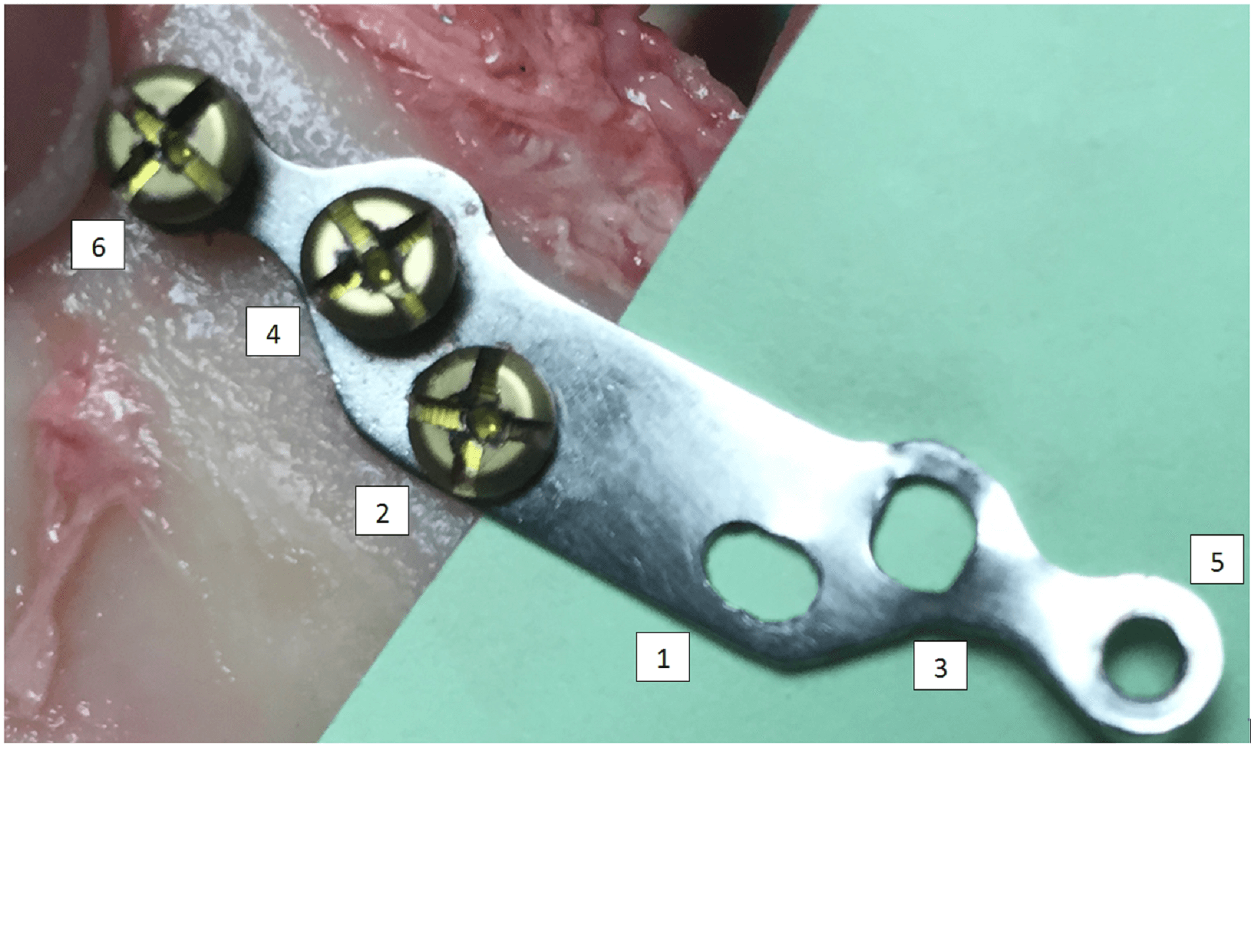
B.

Loads and boundary conditions:

A biting force of 200N was applied at the area of the lower incisive teeth and the mandible fragments were supported by fixing all translations at the nodes on the outer surfaces of the condyles.

Bone properties

For the cortical bone, properties like thickness, density, average elastic moduli, etc. were represented for 31 regions of the vestibular and lingual sides of a semi-mandible. An extract of the values used for these parameters is presented in the table below.


The cancellous bone was represented with isotropic properties defined by:

  • Modulus of elasticty: 0.50GPa
  • Density: 1.40g/cm3
  • Poison Ratio: 0.38

Mini-plate and screw properties

Medical grade titanium was utilised for all hardware with elasticity moduli of 113 and 140GPa for the mini-plate and the screws respectively, and a Poison Ratio of 0.32.

Pre-processing

Multiple 64 cartezian coordinate systems were defined for each semi-mandible to represent the orthotropic bone properties of the cortical bone, on the vestibular and lingual sides, using MAT8 cards in MSC Nastran.


Six cylindrical coordinate systems were defined at the axes of the holes for quick generation of local meshing and for the extraction of results around the holes in the cortical bone and mini-plate.


All components were represented with 3D linear elements.


More than 280 coordinate frames around the edge of the fracture surfaces, were required for the definition of GAP elements used to represent the contact between the two fractured segments after the fracture was reduced, and the mini-plate installed.


Additional GAP elements were defined between the cortical bone and screws, and between the slots in the mini-plate and the screws. The normal pressure fields generated by the torque used during the insertion of the screws was incorporated in the analysis. The mini-plate and the screw meshed with 3D elements.


Additional pre-processing was focused on establishing representative numbering systems for the nodes and the elements, especially around the mini-plate holes and the surfaces of the fracture.

Numerical analysis

Non-linear analysis was carried out in 18 stages, using the non-linear solution 106 in MSC Nastran. The stages were at 2, 5, 10, 20, …, 120, 125, 130, 140 and 150% of the biting load.


In each stage there were 100 increments and the convergence criteria required tolerances no larger than 0.01 in displacements, residual forces and in energy (UPW).

The convergence factors obtained in most cases are smaller than 8–10. For more details on the loading steps and final convergence factors, see the pictures on the right.

Loading Details

Conv. Fact 20%
Conv. Fact 150%

Graphical post processing

Maximum principal strains, ranging from 0–300 micro-strains.

Maximum principal strains, ranging from 0–400 micro-strains.

Analytical post processing

Sample of loads extraction (global and at fastener locations).
Sample of cortical strains at the fracture line and around specified holes.

For information of the evolution of maximum principal strains in the angle of the mandible near the fracture line, or the overall stress distributions in the mini-plate for biting forces up to 300 N, watch Figure 38.

Testimonials

Dr. Teodora Pituru


“We collaborated with Mr. Claudiu Gudas on a very important project. I can emphasise the indisputable qualities that impressed me: perseverance, seriousness and dedication to the subject under investigation. In the future, I will certainly also investigate other medical issues alongside Mr. Gudas.”

Website Designed and Developed by