AIRCRAFT INTERIORS
Brief of scope, configuration and representative loads
Figure 1 shows the general characteristics of one, of several, configurations of 19" wide racks installed in the cabin of a commuter class aircraft. These racks were designed to house electronic equipment used in the live data processing and imaging of electromagnetic information—from radar and/or high optical resolution equipment used in high altitude search and rescue operations with poor visibility.
In the case presented, the racks are of light-weight construction. Their bases are attached to the aircraft seat tracks with two additional attachments connected to the fuselage lateral structure.
The purpose of the analysis was to determine the ultimate interface loads at the airframe—for the purpose of showing compliance with the certification requirements applicable to this class of aircraft and operational profile.
The final finite element analysis was conducted as per customer requirements using Strand7, with an alternative code being developed and supplied in MSC Nastran.
The model presented contains 37 major parts, some fabricated from thin sheets of 4130 mild steel (brackets, supports, hat sections, etc.), others from 0.5" thick honeycomb panels with 2024 aluminium facings and core (side panels and shelves), and more than 250 fasteners such as AN3 and AN525 bolts, MS24603 and MS27039 screws, and honeycomb inserts.
Using a well defined system for the ids of the nodes and elements of all components, detailed and extensive, or targeted, summary reports were generated for the relevant results in a semi-automatic manner—using Excel and a suite of VBA subroutines to read, organise and extract the information from the result files.
A representative brief of the 1g inertial forces applied by the equipment to the rack is shown in Figure 2.

Figure 1
Strand7 solution displayed

Figure 2
Pre-processing
For this initial stage, two main pre-processing tasks are exemplified:
The systematic breakdown for all parts of the geometrical features where high stresses or high stress gradients occur often—due to geometrical stress concentrations and/or the presence of interfaces for load transfer at the connections between the components in the assembly. This systematisation is beneficial for the generation of data decks for meshes with similar features, using scripts in a software of choice.
The use of different material property identifiers, for quick selection and constructions of part sub-groups (in Strand7).
Examples of implementation are presented in Figures 3, 4 and 5.
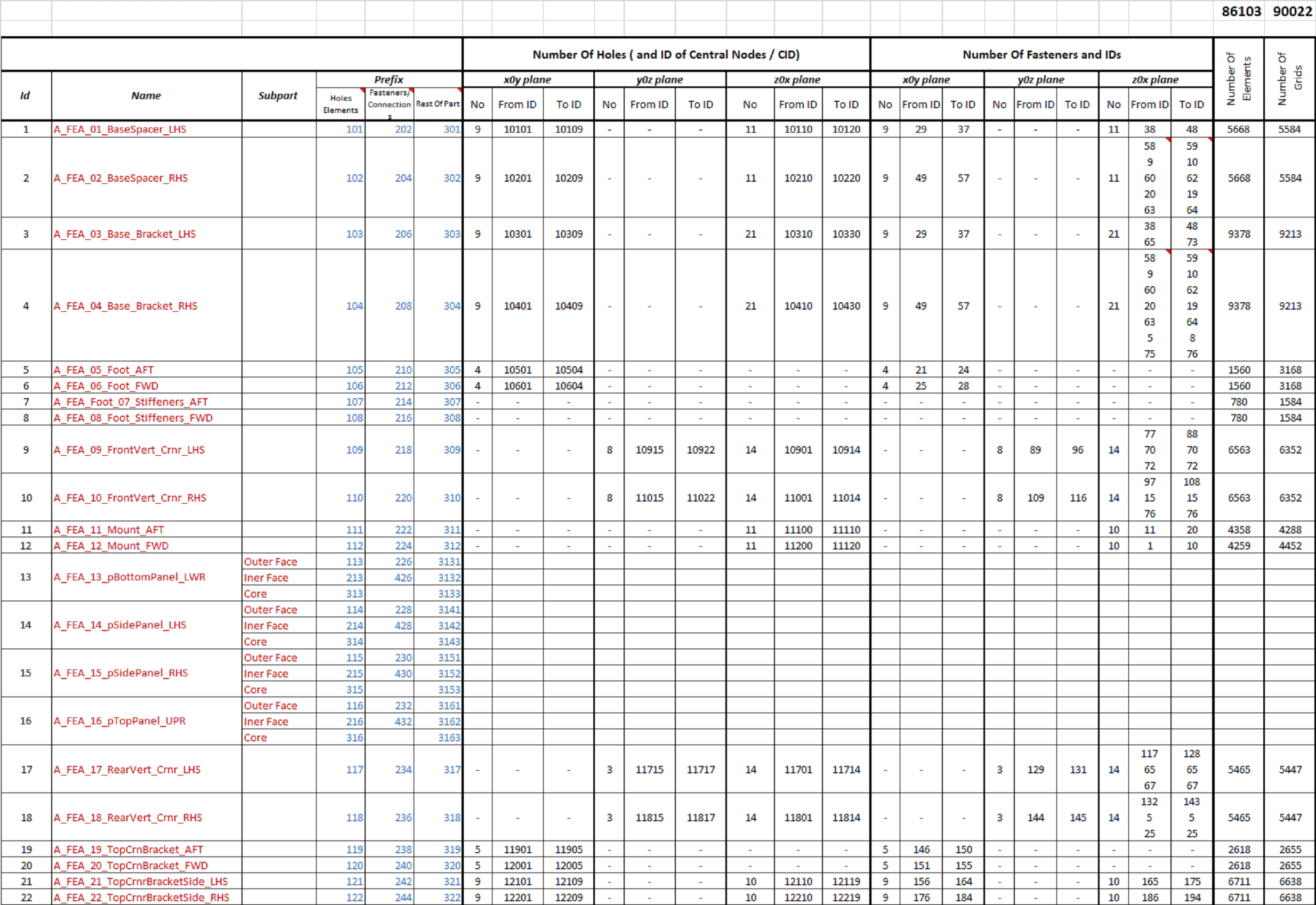
Figure 3
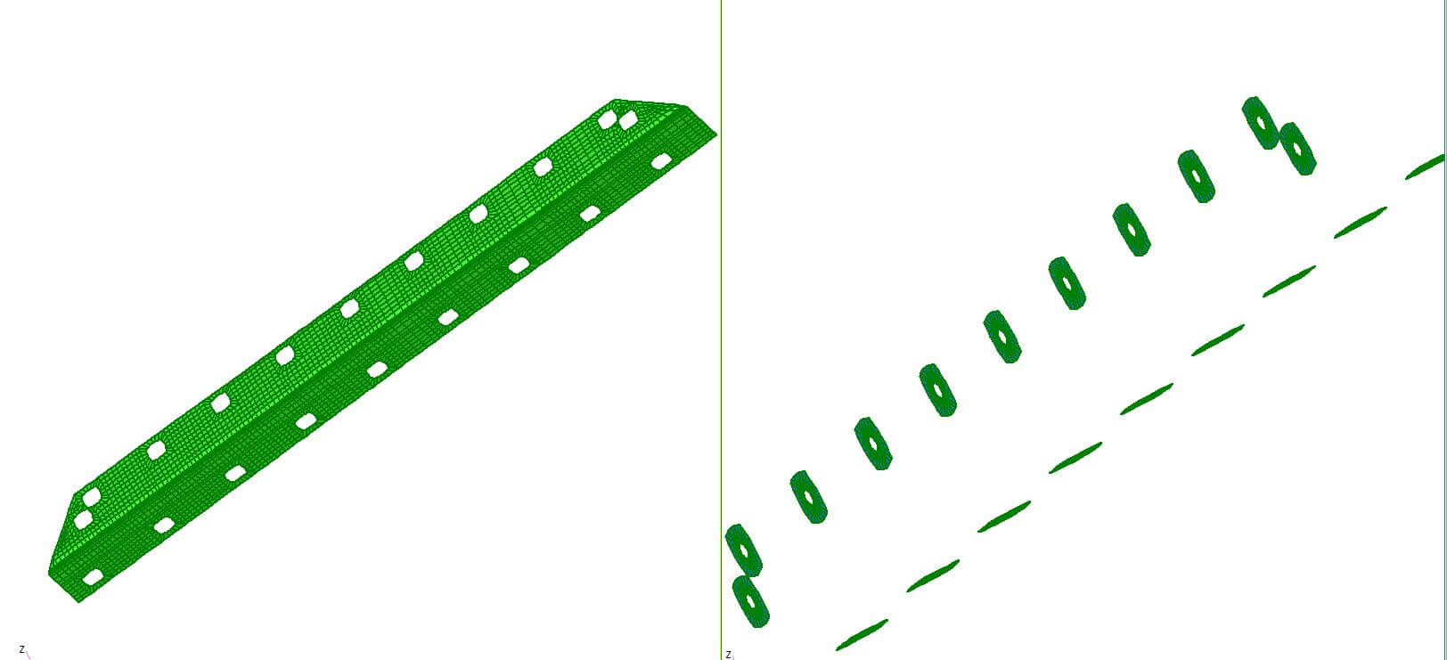
Figure 4
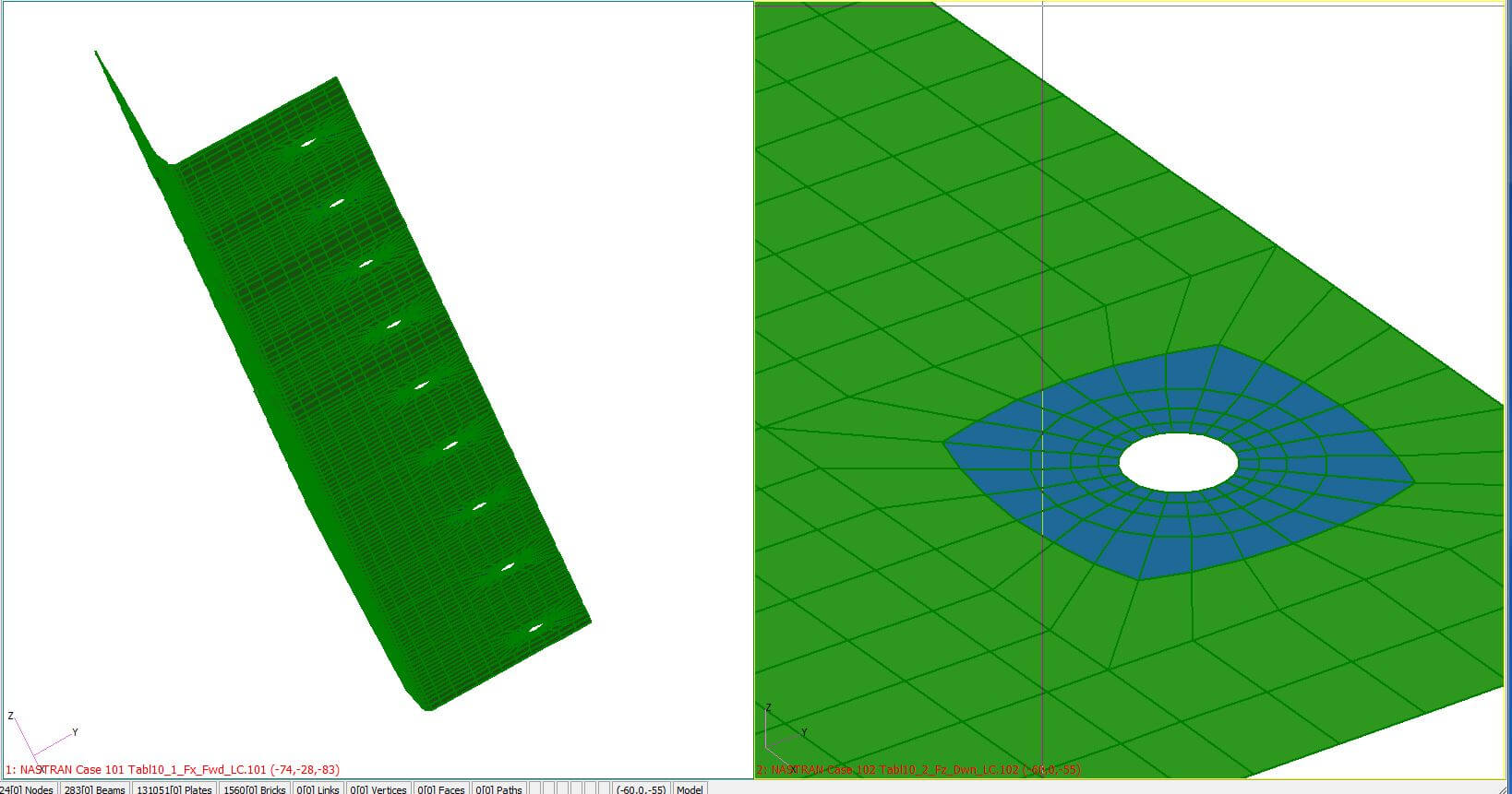
Figure 5
Post-processing
Figures 6 and 7 depict summaries of the analysis results for fastener loads and principal stresses. The systematisation and codification system developed in the pre-processing stage is fed automatically into the tables to provide quick identification of locations, orientation, load case, etc. In this case, relevant von Mises stresses were also included to ascertain if the results of linear analysis are within the validity range of the solution used.
Similar results for the other stress components in material, global or specific coordinate systems. For this analysis over 450 coordinate systems were established in the modelling stage to evaluate the displacements and stresses at each location in the most representative of the cartesian or local polar coordinate systems.
See Figures 8 and 9.

Figure 6
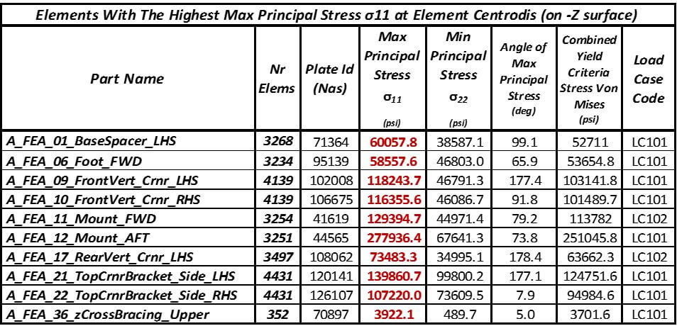
Figure 7

Figure 8
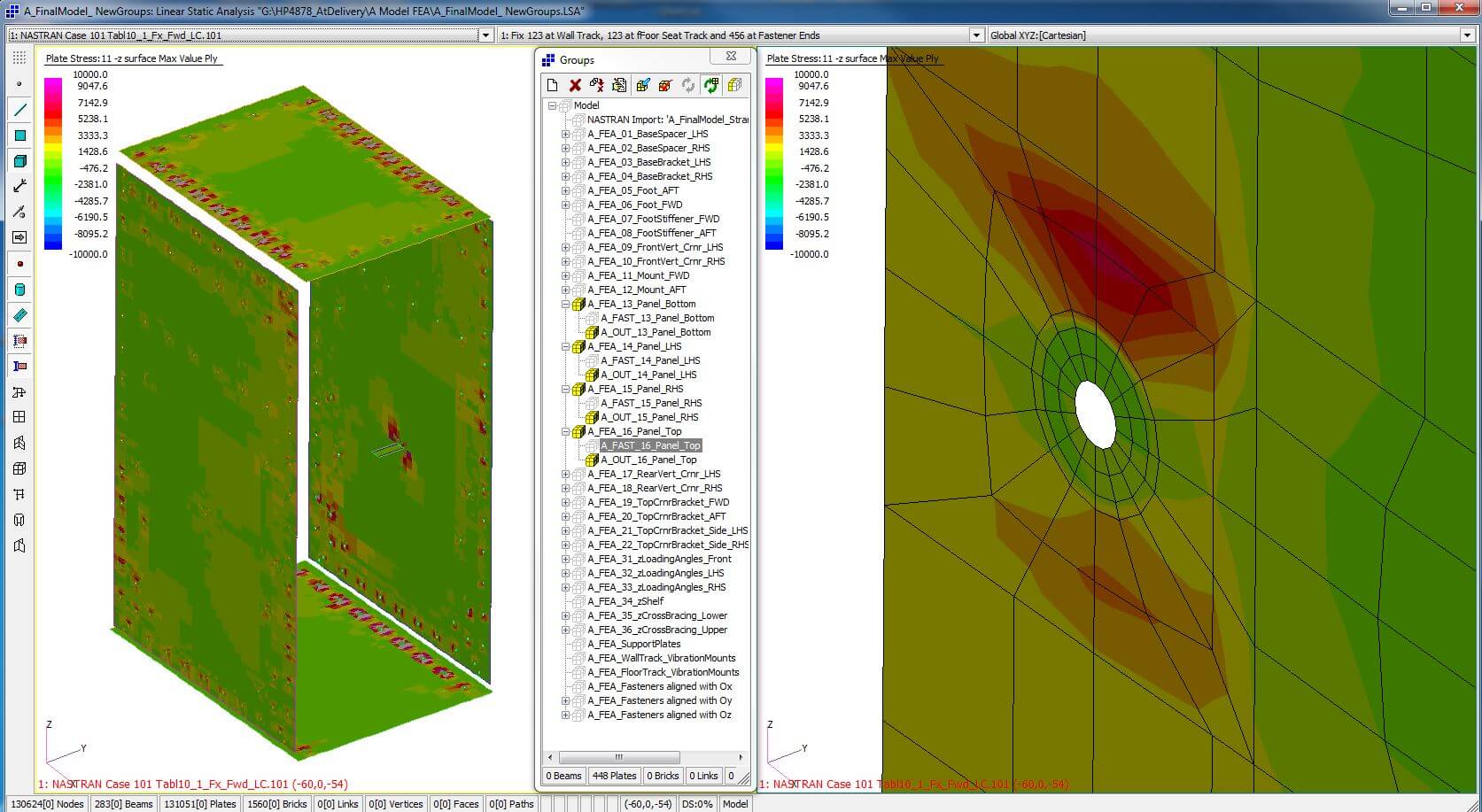
Figure 9


